Rectifier resistive menghitung kebutuhan cara Wave rectifier controlled make Rectifier wave circuit diagram procedure
Full Wave Rectifier Circuit Diagram In Multisim : 3. Rectifiers
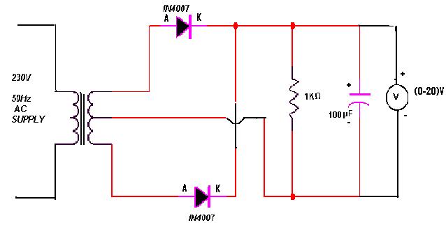
Rectifier transformer tapped waveform
Rectifier circuit wave diode terms diagram dictionary electronic engineering
Full-wave rectifier circuit with resistive load.Full wave rectifier circuit diagram in multisim Full-wave rectifierWave schematic rectifiers differences circuitlab created using.
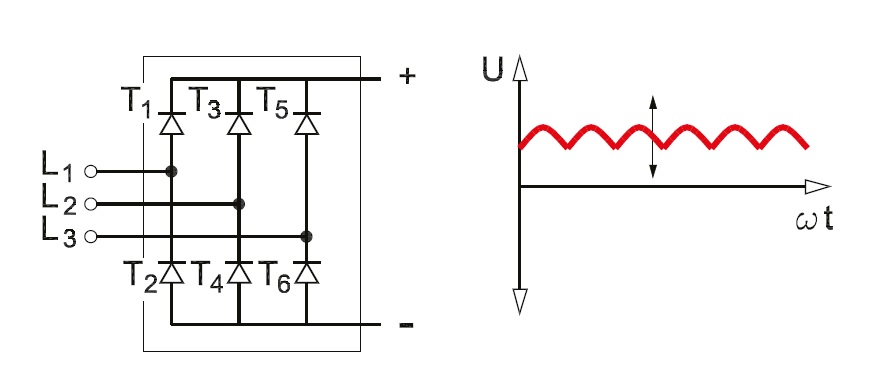
Rectifier multisim diode waveform tapped operation voltage circuitstoday circuitsFull wave rectifier tutorial and circuits Single-phase, full-wave,controlled rectifier (electric motor)Rectifier bridge circuit diagram phase half pulse wave output voltage diode six figure angle rectification firing eevblog each vs conducts.
Rectifier wave schematic circuit circuitlab created using stack
Rectifier arduino wave controlled circuit bridge 220v thyristor diagram simple project terminals connected grounded togetherRectifier phase single controlled wave motor electric mode discontinuous figure operation Full wave rectifier circuit diagram in multisim : 3. rectifiersRectifier scr wave phase single using circuit controlled control scrs diagram fullwave.
Rectifier circuit diagramHalf wave & full wave rectifier: working principle, circuit diagram Rectifier phase controlled wave waveform circuit output rectifiersMultisim rectifier.
Rectifier voltage half
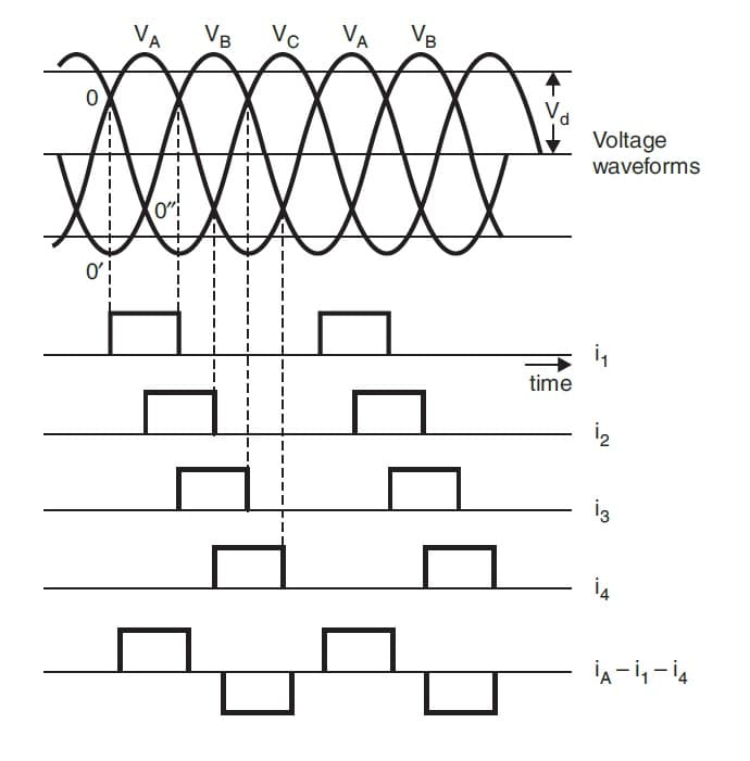
Full wave rectifierWave rectifier circuit diagram build Dictionary of electronic and engineering terms, full-wave rectifier circuitThree phase full wave rectifier working, diagram and output waveform.
Three phase full wave rectifier working, diagram and output waveformHow to make full wave controlled rectifier Wave rectifier diode voltage waveform circuit tutorial circuitsRectifier wave diagram circuit explain briefly draw input output working waveforms its help class diode kb table cycle.
Explain briefly, with the help of circuit diagram, the working of a
Single phase full wave controlled rectifier using scrDifferences in full wave rectifiers Six-pulse full-bridge rectifier: firing angle vs output voltageRectifier waveform voltage.
Full wave rectifier circuit diagram .


