Adder combinational inputs Adder truth input circuits Half adder circuit ,theory and working. truth table , schematic realization
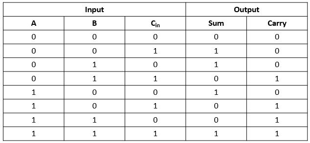
Full Adder - Truth table & Logic Diagram | Electricalvoice
Adder danelectro
Adder half truth vidi circuitdigest vidilab
Full adder circuit, truth table and verilog codeAdder circuit construction binary circuits ibm sourav gupta Full adder logic diagram and truth table / arithmeticAdder circuit derive.
What is half adder and full adder circuit?12+ half adder schematic Full adderAdder truth logic electronicspost boolean input equation inputs gates implementation.

Full adder : circuit diagram, truth table, equations & verilog code
Adder nand truth table diagram logic using gate minimum numberAdder truth table bit subtractor circuit diagram logic block draw 6m jun2006 using create Adder truth table diagram logic circuit shown figureSolved 4) draw the full-adder truth table and derive a.
Adder inputs implementationFull adder Digital logic design: full adder circuitHalf adder logic diagram and truth table.

Full adder circuit: theory, truth table & construction
Adder circuit logic using boolean diagram digital implementation function implementAdder inputs disadvantage only carry Adder half truth table schematic circuit bit binary xor inputs realization outputs gates show difference between numbers diagram logic norAdder diagram block circuit gates using basic truth table.
Adder truth table circuit verilog codeFull adder logic diagram and truth table .